Sheet Metal Design Keeps Going Wrong? 7 Rules Novices Must Read
Common mistakes of sheet metal design novices can be avoided with 7 core rules: follow the "4T Rule" to prevent bending deformation, mark datum and thickness in 3D models for process adaptation, unify bend radius to reduce mold costs, fully label hardware specifications to avoid installation misalignment, choose surface treatment by scenario to control costs, balance performance and manufacturability for material selection, and ensure U-channel width-to-height ratio ≥2:1 for strength. Mastering these rules reduces 90% of design errors, aligning with the industry's demand for lightweight and cost-efficiency.
Novices in sheet metal design often face repeated revisions due to ignoring "manufacturability"—an electronics factory’s chassis design had holes too close to bend lines, causing cracks at the hole edges after bending and rework losses exceeding 20,000 RMB; an equipment manufacturer customized 5 types of molds because they didn’t unify the bend radius, increasing costs by 30%. In fact, most mistakes stem from not mastering basic design rules. The following 7 actionable guidelines cover core links such as material selection, structural design, and process adaptation, helping novices avoid 90% of common errors and align with the current sheet metal industry’s hot demands for "lightweight, low-cost, and fast delivery."
1. Follow the "4T Rule" for Feature Layout to Avoid Bending Deformation
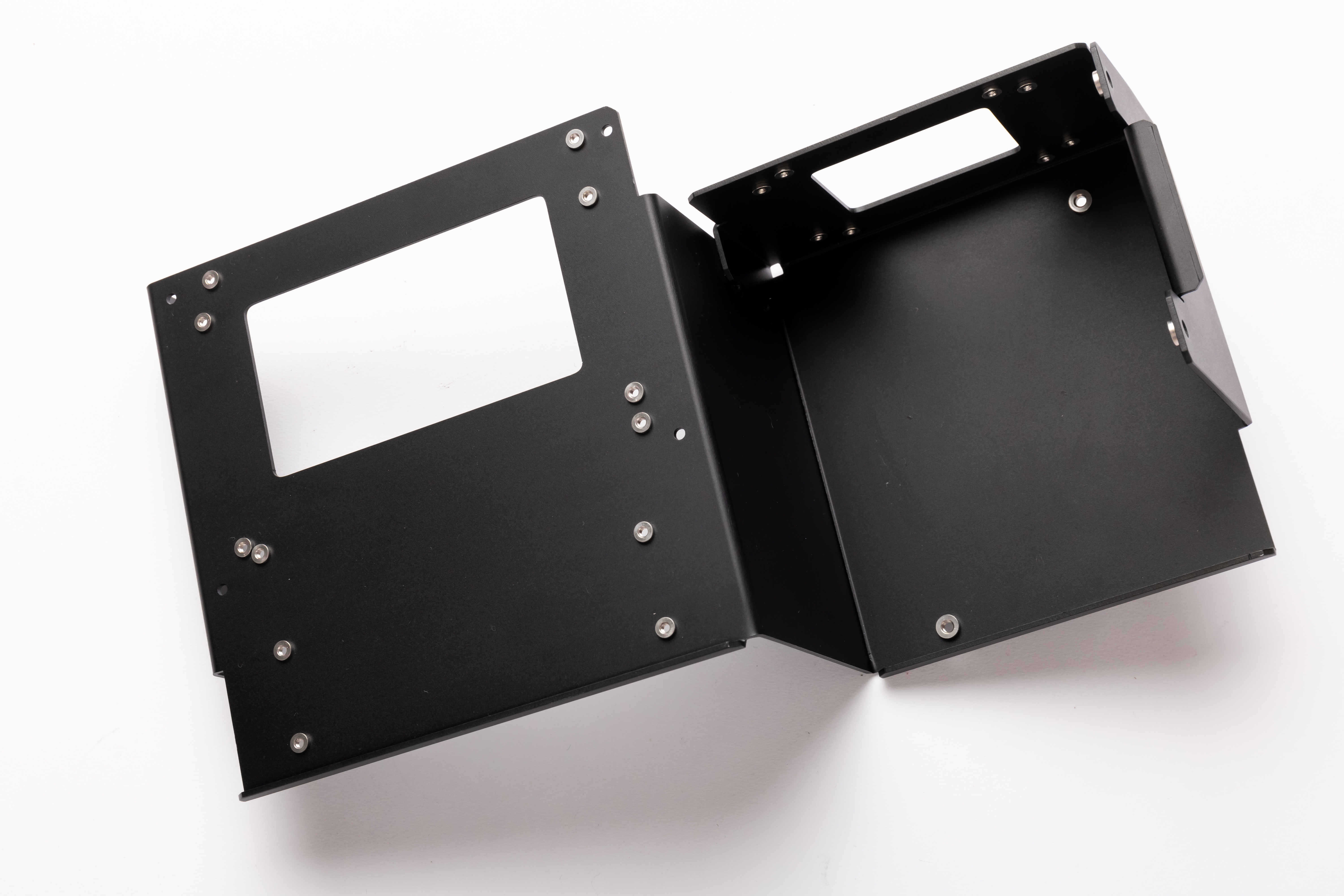
All features such as holes and slots must be at least "4 times the material thickness (4T)" away from the bend line—for a 1mm thick steel plate, the distance from the hole edge to the bend line must be ≥4mm. Violating this rule will cause feature deformation (e.g., hole position deviation, slot cracking) due to material stretching during bending. A new energy company’s battery bracket initially had holes only 2mm away from the bend line, resulting in 30% of parts being scrapped after bending; after adjusting to 5mm, the pass rate reached 99%. This rule applies to all types of sheet metal parts such as chassis and brackets, and is a recognized basic standard in the industry.
2. 3D Models Must Mark "Bending Datum" and "Thickness Consistency"
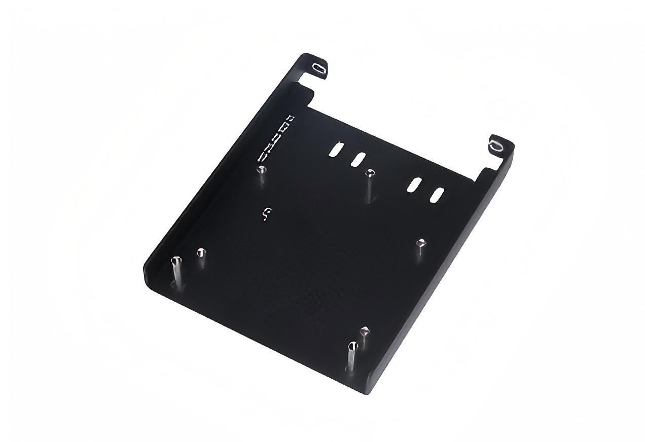
Novices easily overlook the process information in 3D models: first, the "datum plane" at the bending position must be clearly marked to help the factory determine the bending sequence and avoid direction errors; second, the thickness of the entire sheet metal part must be uniform (e.g., all using 1.2mm cold-rolled steel plates, not 0.8mm locally), otherwise it will increase the number of material changes for laser cutting and extend the delivery time. A medical equipment factory did not mark the datum plane in the model, resulting in 200 shields being bent in the wrong direction, and reprocessing took 1 week
3. Unify the Bend Radius to Reduce Mold Costs
Different bend radii correspond to different molds. If novices randomly set radii (e.g., mixing 1mm, 2mm, 3mm) during design, the factory will need to change molds frequently, reducing efficiency by 40%. It is recommended to prioritize "standard bend radii" (e.g., R1.5 for 1mm thick materials, R2.5 for 2mm thick materials) and unify the radius for the entire part. A sheet metal factory’s statistics show that the processing cycle of parts with a unified radius is 25% shorter than that of parts with multiple radii, and mold costs are reduced by 50%, in line with the current industry hot demand for "cost reduction and efficiency improvement."
4. Mark "Full Information" for Hardware Specifications to Avoid Installation Misalignment
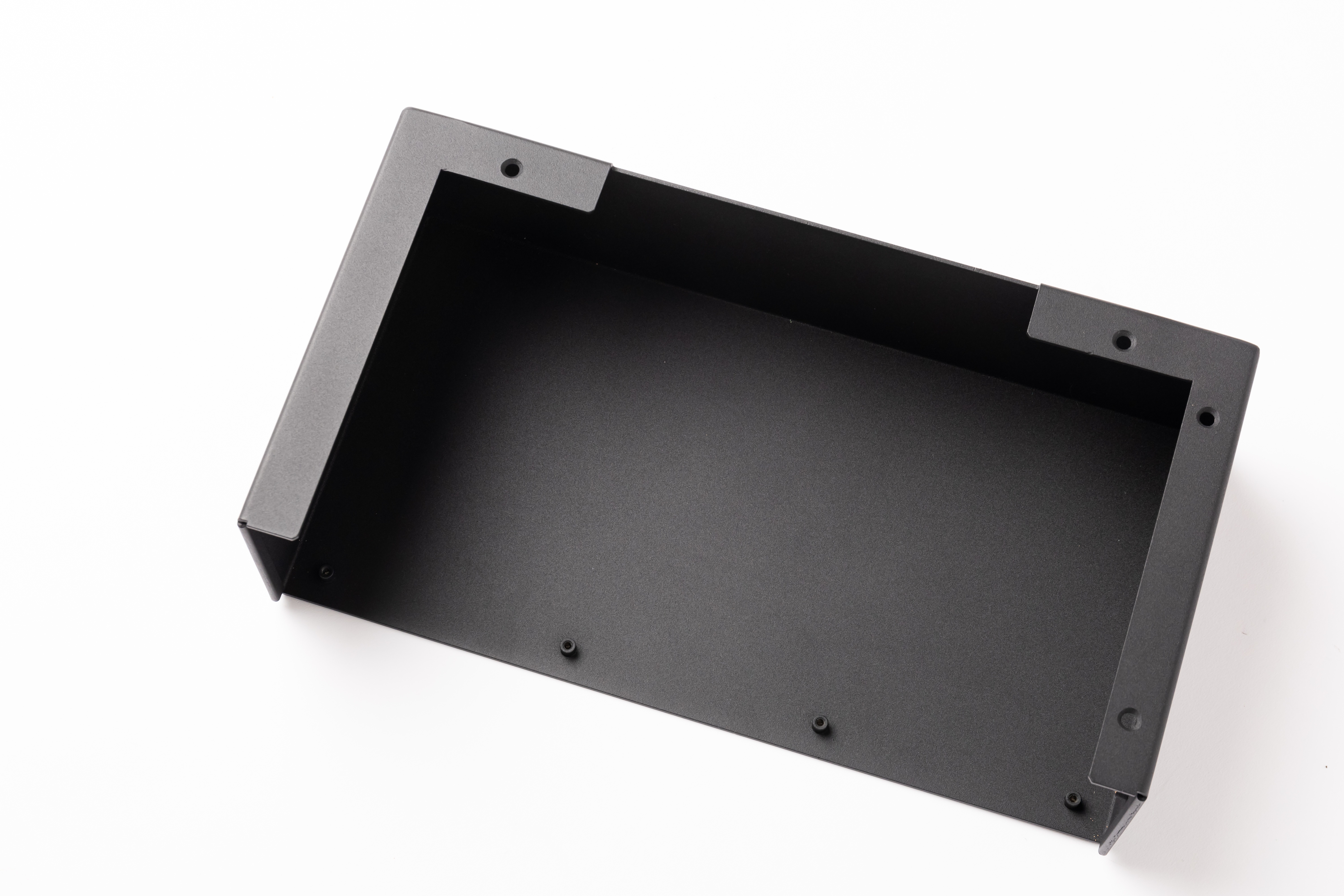
When designing screw holes and stud positions, it is necessary to specify the hardware model (e.g., "M4 self-tapping screw, countersink depth 2mm") and installation gap (e.g., "hole diameter 0.2mm larger than the screw"), rather than just drawing the hole position. A cabinet factory did not mark the stud height, so the 1000 purchased studs were too long to install and had to be re-customized, resulting in a loss of 15,000 RMB. This rule adapts to the current "modular assembly" trend and reduces later debugging time.
5. Match Surface Treatment to "Usage Scenario" and Avoid Blindly Choosing Expensive Options
Novices often follow the trend to choose expensive treatments such as "anodizing," but in fact, they need to choose based on scenarios: sheet metal used outdoors (e.g., charging pile enclosures) should use "powder coating" (strong weather resistance, low cost); medical equipment should use "chemical conversion treatment" (no risk of coating peeling, meeting ISO 13485 standards); electronic components should use "galvanizing" (corrosion resistance and conductivity). An outdoor equipment manufacturer mistakenly used anodizing for the chassis, which cost 40% more than powder coating, and the coating peeled off after exposure to the sun, requiring full rework later.
6. Material Selection Must Balance "Performance" and "Manufacturability"
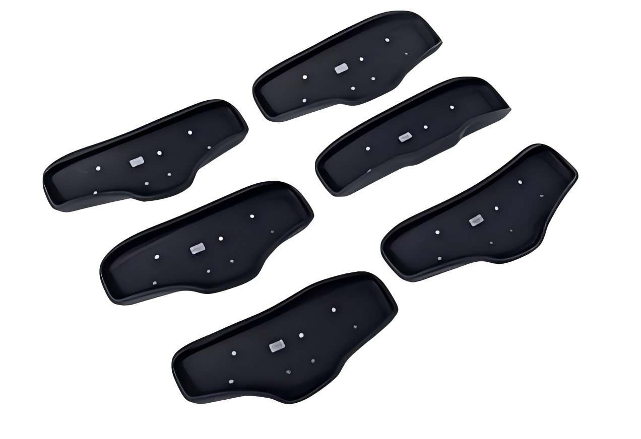
Don’t just focus on strength; also consider processing difficulty: stainless steel (304) has high strength but slow laser cutting speed, suitable for corrosion-resistant scenarios (e.g., food equipment); cold-rolled steel (SPCC) is easy to cut and bend, low cost, suitable for ordinary parts such as chassis and brackets; aluminum alloy (5052) is lightweight (30% lighter than steel), but prone to cracking during bending and needs annealing in advance. A drone manufacturer initially used 6061 aluminum alloy for the frame, with a bending scrap rate of 20%; after switching to 5052 and annealing, the scrap rate dropped to 2%, aligning with the "lightweight design" hot trend.

 Esperanto
 Shqiptare
 Euskara
 Zulu
Zulu
 Latinus
 Cymraeg
 தமிழ்
தமிழ்
 Slovak
 Slovak
 Afrikaans